| 項目 | GY-31TCS230 | Grove 12C Color | TCS3200 |
| 官網 | https://surtrtech.com/2019/08/04/arduino-color-detection-using-tcs3200-tcs230-gy-31-color-sensor-module-rgb-project/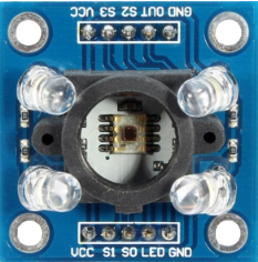 |
https://wiki.seeedstudio.com/cn/Grove-I2C_Color_Sensor/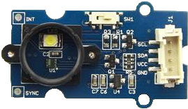 |
https://wiki.dfrobot.com/TCS3200_Color_Sensor__SKU_SEN0101_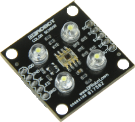 |
| 本站下載 | Grove_I2C_Color_Sensor-master | ||
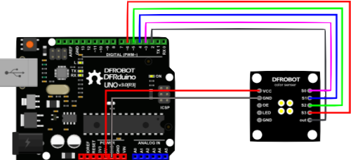
| 接線方式 | 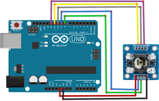 |
 |
|
| 範例程式 |
/* This code works with GY-31 TCS3200 TCS230 color sensor module * It select a photodiode set and read its value (Red Set/Blue set/Green set) and displays it on the Serial monitor * Refer to www.surtrtech.com for more details */ #define s0 8 //Module pins wiring #define s1 9 #define s2 10 #define s3 11 #define out 12 int data=0; //This is where we're going to stock our values void setup() { pinMode(s0,OUTPUT);//pin modes pinMode(s1,OUTPUT); pinMode(s2,OUTPUT); pinMode(s3,OUTPUT); pinMode(out,INPUT); Serial.begin(9600); //intialize the serial monitor baud rate digitalWrite(s0,HIGH); //Putting S0/S1 on HIGH/HIGH levels means the output frequency scalling is at 100% (recommended) digitalWrite(s1,HIGH); //LOW/LOW is off HIGH/LOW is 20% and LOW/HIGH is 2% } void loop() //Every 2s we select a photodiodes set and read its data { digitalWrite(s2,LOW);//S2/S3 levels define which set of photodiodes we are using LOW/LOW is for RED LOW/HIGH is for Blue and HIGH/HIGH is for green digitalWrite(s3,LOW); Serial.print("Red value= "); GetData();//Executing GetData function to get the value digitalWrite(s2,LOW); digitalWrite(s3,HIGH); Serial.print("Blue value= "); GetData(); digitalWrite(s2,HIGH); digitalWrite(s3,HIGH); Serial.print("Green value= "); GetData(); Serial.println(); delay(2000); } void GetData(){ data=pulseIn(out,LOW); //here we wait until "out" go LOW, we start measuring the duration and stops when "out" is HIGH again Serial.print(data); //it's a time duration measured, which is related to frequency as the sensor gives a frequency depending on the color Serial.print("\t"); //The higher the frequency the lower the duration delay(20); } |
int s0=3,s1=4,s2=5,s3=6; int out=2; int flag=0; byte counter=0; byte countR=0,countG=0,countB=0; void setup() { Serial.begin(115200); pinMode(s0,OUTPUT); pinMode(s1,OUTPUT); pinMode(s2,OUTPUT); pinMode(s3,OUTPUT); } void TCS() { flag=0; digitalWrite(s1,HIGH); digitalWrite(s0,HIGH); digitalWrite(s2,LOW); digitalWrite(s3,LOW); attachInterrupt(0, ISR_INTO, CHANGE); timer0_init(); } void ISR_INTO() { counter++; } void timer0_init(void) { TCCR2A=0x00; TCCR2B=0x07; //the clock frequency source 1024 points TCNT2= 100; //10 ms overflow again TIMSK2 = 0x01; //allow interrupt } int i=0; ISR(TIMER2_OVF_vect)//the timer 2, 10ms interrupt overflow again. Internal overflow interrupt executive function { TCNT2=100; flag++; if(flag==1) { countR=counter; Serial.print("red="); Serial.println(countR,DEC); digitalWrite(s2,HIGH); digitalWrite(s3,HIGH); } else if(flag==2) { countG=counter; Serial.print("green="); Serial.println(countG,DEC); digitalWrite(s2,LOW); digitalWrite(s3,HIGH); } else if(flag==3) { countB=counter; Serial.print("blue="); Serial.println(countB,DEC); Serial.println("\n"); digitalWrite(s2,LOW); digitalWrite(s3,LOW); } else if(flag==4) { flag=0; } counter=0; } void loop() { TCS(); while(1); } |